
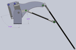
Now that the stability issues have been figured out and I am happy with the amount of force I can get out of the linkage, I think it's time to get a better idea of what I have built. I am reasonably confident that 4 or more of these mechanical legs mounted to a base of some sort could be controlled well enough to make the entire contraption to walk so I took the time to model in SolidWorks the leg mechanism as it is today. The black carbon fiber leg tubes and the ball joints are all defined so that I can move the leg in the CAD software and accurately measure the rotational angles of the Futaba servo motors at any leg position. To walk smoothly both servos need to move at the same time to take a step due to the linkage mechanism. The tip of the leg (the foot essentially) should move in a reasonably straight line as the leg takes a step otherwise the robot will waddle and jerk as it goes along. Probably not a big problem at first but eventially if the robot gets some kind of sensor system to monitor where it is the waddle and erratic motion could be a problem. I can think of a few other ways than CAD to figure this out like move the actual prototype leg and try to measure the angles or open up the servos and measure the resistance of the position pots that are inside.

The two Futaba servos are mounted on top of one another with the top one causing the entire leg to Rotate down and the bottom one (by linkages) causing the leg and foot to extend. There are two aluminum plates that and on the ends of the servos and spaced apart with aluminum and plastic standoffs. I went with this approach to keep the amount of metal bending to a minimum which should make these more rigid.

The pivots or bearings are made from nylon standoffs that happen to fit nicely into K'nex pieces with a little bit of cutting. The loose fit and the low friction make good bearings. The attach points to the carbon fiber tubes took a bit of experimentation but I settled on bending some metal, wrapping it onto the carbon tube in an area that had been sanded, wrappint it up with fishing line and the spreading clue over both the metal and the line. Before the glue dries sliding heat shrink tubing over all of it and heating - shrinking it down. This seems to have made a reallt strong bond to the tube and is working well.
 I have created some relationships in the CAD model that I can control with dimensions and measure the angles as the foot moves. All the angle information and the actual foot position will go into a spreadsheet to define a state machine based on the combination of servo rotations. Put another way the table will be a look up of servo angles with the result being the location of the foot in 3D space. This table or the data simplified to a formula will go into the robot controller that will eventually run this thing.
 This is a lot of information and I am tired so I am sure it's not making a lot of sense the way. Eventually it will all work.... ;-)

No comments:
Post a Comment